Tube Light Choke Wiring Diagram
Tube light wiring connection diagram with electrical choke tube light fluorescent tube light fluorescent tube. 40 watt electronic ballast circuit.
Tube Light Wiring Connection with Diagram (Electrical

The choke is in fact a large.
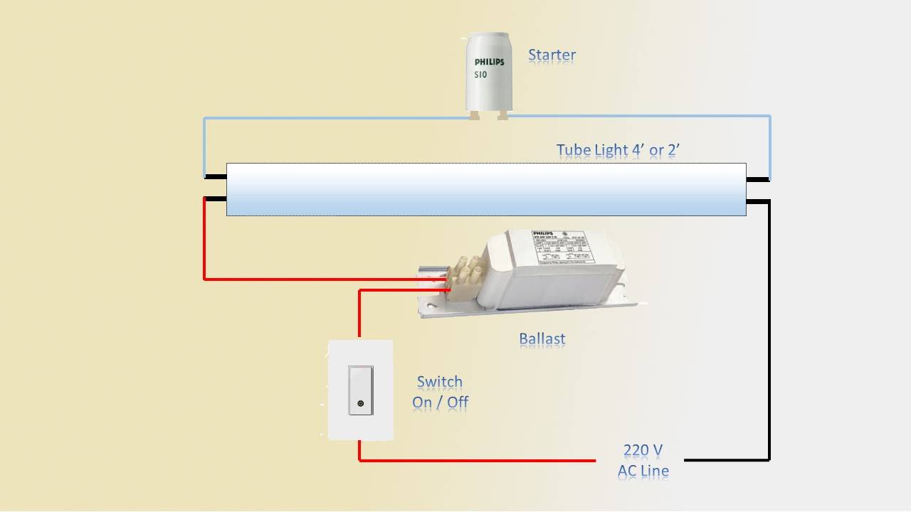
Tube light choke wiring diagram. Tube light connection with electronic choke: Wiring diagram of single tube light installation with electronic. The connection diagram of tube light with electronic choke is very simple.
Typical compact flash lamp ballast circuit 10 15 compact. Wiring diagram of single tube light installation with electromagnetic ballast tube light light switch wiring lighting diagram. Connection of tube light is very simple because it has few wiring points only.
Once again the choke provides low. About diagram circuit light uv choke. A wiring diagram is a streamlined traditional pictorial representation of an electrical circuit.
40w fluorescent light electron ballast electrical schematic. Electronics circuits electronic ballasts electronic choke. Typical compact flash lamp ballast circuit 10 15 compact.
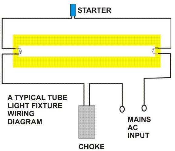
Schematic wiring diagram for two tube light with one ballast (choke). Here is one example of a tube light fixture consisting of a large heavy square “choke” or “ballast” and a small cylindrical “starter.” let’s try to understand how the whole system works. Please refer to the circuit diagram on the right as you read the following points.
Tube light wiring connection earth bondhon 1 what is a led driver. The pcb layout of the proposed electronic fluorescent ballast is also provided along with the torroid and the buffer choke winding details.
Here is no need of tube light starter. Electronics circuits electronic ballasts electronic choke. Single ended led tube wiring if shunted lampholders are used in a light fixture they must be replaced with non shunted at the location where line and neutral are to be connected.
Tube light circuit wiring diagram. 40w fluorescent light electron ballast electrical schematic. Net is free online diagram software for making flowcharts, process diagrams, org charts, uml, er and network diagrams.
Nec rules for installing lighting on circuits greater than. Five important life lessons fluorescent light installation diagram taught us. Single tube fluorescent light wiring diagram by vallery masson on june 26, 2021 the fluorescent tube has two filaments with four terminals the starter is connected between two filaments the ballast is connected between main ac supply and one filament in tube.
From the junction box the neutral wire is not taken out to the switch board, rather it is taken out from the junction box and carried out to the port 2 of the tube light, as per figure above. Tube light circuit wiring diagram. A diagram that represents the elements of a system using abstract graphic drawings or realistic pictures.
In this video i will show you fluorescent tube light wiring connection and also provide circuit diagram of connection. Tube light wiring connection with diagram electrical choke electronic choke led. Different electrical symbols are used to make the wiring diagram below:.
Tube light wiring connection earth bondhon Wiring diagram of single tube light installation with electromagnetic ballast: Led tube light wiring diagram.
Wiring diagram here two tube lights are used, in our case each one is 20 watts, each tube light will have two filament with four terminals, connect starter element to any on side of tube light , after that link phase line to the ballast (choke) through switch. Although it operates at 230 v, 50 hz, some auxiliary electrical components are used to insert in this installation to support the tube light operational principle. The choke is in fact a large.
Here is no need of tube light starter. Two tube with one ballast (choke) wiring diagram here in this tube light wiring diagram you will find two fluorescent tubes are connected with one choke or ballast, two separate starters are used for each tube and finally connected to 230v power supply through a. Wiring diagram for a single tube light circuit tube light circuit diagram circuit tube light circuit wiring diagram youtube led tube light tube light fluorescent tube light connection of tube light tube light fluorescent tube light connection 9 watt cfl bulb ballast circuit diagram in 2021 cfl bulbs cfl electrical wiring diagram electronic choke wiring […]
Tube lights are most used light source and here tube light connection circuit and wiring diagram given with explanation. Tube light connection diagram with electronic choke. Wiring diagram for led tube lights sample.
Nec rules for installing lighting on circuits greater than. Pin on house wiring of electrical main board electrical board wiring bangladesh ad get tube lights. Wiring diagram of single tube light installation with electromagnetic ballast how to install a single tube light with electromagnetic ballast from the junction box the neutral wire is not taken out to the switch board, rather it is taken out from the junction box and carried out to the port 2 of the tube light, as per figure above.
Initially no current flows through the tube only a current flows through the choke. As you see in the above diagram the input of the electronic choke is connected to the switch board for power supply. Please refer to the circuit diagram on the right as you read the following points:
The purpose of the square is to provide a very high voltage at the beginning of the filaments (towards both ends of the tube light). Electronic choke has one input and two output. How to install a single tube light with electromagnetic ballast.
Tube light connection diagram shown here is suitable for common type fluorescent tubelight. Here in this tube light wiring diagram, you will find two fluorescent tubes are connected with one choke or ballast, two separate starters are used for each tube and finally connected to 230v power supply through a switch to on/off both tubes together. The proposed 40 watt electronic ballast is designed to illuminate any 40 watt fluorescent tube, with high efficiency, and optimal brightness.
A wire already connects port 2 and pin 1 of the.
87 Chevy Truck Fuse Box schematic and wiring diagram
keelapavoor engineers club House Wiring and Troubleshooting

John Deere X300 Wiring Diagram Web

How Do Fluorescent Tube Lights Work? Explanation & Diagram
2 Lamp Ballast Wiring Diagram Wiring Sample

Tube Light Choke Circuit Diagram 12 Volt Fluorescent

Wiring Diagram of Twin Tube Light Electrical Revolution

44+ Electronic Choke Wiring Diagram Gif easywiring

44+ Electronic Choke Wiring Diagram Gif easywiring

Wiring Diagram Of Tube Light With Electronics Choke
44+ Electronic Choke Wiring Diagram Gif easywiring

Wiring Diagram Of Tube Light With Electronics Choke

Double Tube Light Circuit Diagram

Learn Electrician Tube Light wiring connections

Wiring Lighting Circuit Diagram Wiring Diagram Schemas

20 Watt Tubelight Emergency Light Circuit Diagram

Tube Light Wiring Connection with Diagram (Electrical

Tube Light Wiring Diagram Complete Wiring Schemas

Learn Electrician Tube Light wiring connections
